Official Luthiers Forum!

Owned and operated by Lance Kragenbrink
It is currently Wed Jul 23, 2025 12:15 pm


All times are UTC - 5 hours


Forum rules


Be nice, no cussin and enjoy!


Post new topic Reply to topic  [ 37 posts ]  Go to page 1, 2  Next
Author Message
PostPosted: Fri Jan 09, 2009 2:05 am 
Offline
Contributing Member
Contributing Member

Joined: Wed Mar 19, 2008 11:49 am
Posts: 897
Location: Northen Cal.
I have a question. Why are bridges bellied towards the butt of a guitar. It gives more glue surface but if put on the other side it would do that plus provide mechanical leverage against the bridge pulling up. In visualizing these types of things it is helpful to exaggerate the thing you are thinking about. In this case if you make a bridge with a belly 6" long and try to tip it over towards the direction the strings are pulling it will tip as easily as a bridge with no belly. (With no glue of course) Only by gluing is this design stronger than a non bellied bridge. However if you make the 6" extenuation in the other direction towards the sound hole you can't tip the bridge over at all even without glue. All the forces become mostly shear and the bridge is trying to slide forward. Much easier to stop sliding than lifting. In lifting the actual fibers of the top can fail but it would take many, many times the force to make them fail in shear.
Is there a sonic reason for the belly to the back.
Thanks,
Link

_________________
Cut to size.....Beat to fit.....Paint to match.


Top
 Profile  
 
PostPosted: Fri Jan 09, 2009 4:50 am 
Offline
Koa
Koa
User avatar

Joined: Tue Sep 30, 2008 8:57 am
Posts: 544
Location: Auchtermuchty, Fife, Scotland
Focus: Build
Status: Amateur
Link Van Cleave wrote:
I have a question. Why are bridges bellied towards the butt of a guitar. It gives more glue surface but if put on the other side it would do that plus provide mechanical leverage against the bridge pulling up. In visualizing these types of things it is helpful to exaggerate the thing you are thinking about. In this case if you make a bridge with a belly 6" long and try to tip it over towards the direction the strings are pulling it will tip as easily as a bridge with no belly. (With no glue of course) Only by gluing is this design stronger than a non bellied bridge. However if you make the 6" extenuation in the other direction towards the sound hole you can't tip the bridge over at all even without glue. All the forces become mostly shear and the bridge is trying to slide forward. Much easier to stop sliding than lifting. In lifting the actual fibers of the top can fail but it would take many, many times the force to make them fail in shear.
Is there a sonic reason for the belly to the back.
Thanks,
Link


Gibson used/use a 'backward' facing bridge o some models - always looked a bit strange to me, butnI am sure it must be to do with the mechanical impact of what you suggest - the perenniel luthiers compromise I guess - constantly seeking out ways to lighten the top and free the vibes, Versus maintaining structural integrity.....


Top
 Profile  
 
PostPosted: Fri Jan 09, 2009 10:44 am 
Offline
Contributing Member
Contributing Member

Joined: Wed Mar 19, 2008 11:49 am
Posts: 897
Location: Northen Cal.
I get that. I wonder why towards the back. You put it towards the front and it reduces the glue line load on the back. To the back obviously helps but mechanically towards the front is better. Why not a shape like a biscuit jointer biscuit ? I wondered if it was for sonic reasons because mechanically to the front is better.
Link

_________________
Cut to size.....Beat to fit.....Paint to match.


Top
 Profile  
 
PostPosted: Fri Jan 09, 2009 11:04 am 
Offline
Brazilian Rosewood
Brazilian Rosewood
User avatar

Joined: Thu Mar 22, 2007 10:59 pm
Posts: 2103
Location: Bucharest, Romania
Country: Romania
Focus: Build
Status: Professional
Why is better towards the front. Under tension, the bridge is trying to compress that area, not pull it apart?

_________________
Build log


Top
 Profile  
 
PostPosted: Fri Jan 09, 2009 11:08 am 
Offline
Old Growth Brazilian

Joined: Tue Dec 28, 2004 1:56 am
Posts: 10707
Location: United States
Actually putting the added mass towards the front does not help. It reduces the footprint where the shear loading is the greatest. Do this and you have more shear load per square inch therefore greater chance of the bridge pulling loose at the rear. the bell out towards the rear adds footprint or glue surface thus reducing the shear load per square inch or in other words spreads the shear load over a larger area. Personally I like Yairi's solution to the issue. A flanged column that protrudes from the inside of the top for the pins and separate U shaped platform for the saddle. in this configuration both joints seem mainly compression loading
Attachment:
yairi bridge.jpg


You do not have the required permissions to view the files attached to this post.


Top
 Profile  
 
PostPosted: Fri Jan 09, 2009 11:55 am 
Offline
Cocobolo
Cocobolo

Joined: Wed Jan 23, 2008 3:28 pm
Posts: 133
Location: Massachusetts
Michael...

I'm not getting why the configuration of the bridge would change the type of load (i'm not an engineer if it hasn't been obvious so far....). I undertand the part for the bridge, since that really hasn't changed from the stress on the front of a normal bridge, and the disconnect only applies the downard force now. The pin section though, are you calling it compression just because the strings now pull the "inner bridge" upwards against the top? The direction of the force hasn't changed though, just the type, correct?

It's really cool to see that. I was actually thinking about somthing similar but was going to put the entire bridge underneath. I was going to wait until i got to that part of the build to post a sketch and questions, but didn't want to frustrate you all too early [headinwall] with more "untraditional" thinking. I like his design better.

thnx


Top
 Profile  
 
PostPosted: Fri Jan 09, 2009 12:27 pm 
Offline
Old Growth Brazilian

Joined: Tue Dec 28, 2004 1:56 am
Posts: 10707
Location: United States
Rob Lak wrote:
Michael...

I'm not getting why the configuration of the bridge would change the type of load (i'm not an engineer if it hasn't been obvious so far....). I undertand the part for the bridge, since that really hasn't changed from the stress on the front of a normal bridge, and the disconnect only applies the downard force now. The pin section though, are you calling it compression just because the strings now pull the "inner bridge" upwards against the top? The direction of the force hasn't changed though, just the type, correct?

It's really cool to see that. I was actually thinking about somthing similar but was going to put the entire bridge underneath. I was going to wait until i got to that part of the build to post a sketch and questions, but didn't want to frustrate you all too early [headinwall] with more "untraditional" thinking. I like his design better.

thnx


Well I will look for a cross section picture for you. The part tht the pins and string balls are in contact with is a separate single piece from the part that the saddle is attached to. It is flange on the inside of the top and a column that protrudes through the top because it is separate from the part that supports the saddle it see pretty much only compressive loading from the ball ends of the sting. now it does see some rotational force but due to the flange on the inside all the force that was in shear on a typical bridge is compressive on this part of the Yairi bridge because there is no part glued to the outside top to be in shear loading created by the rotation of the bridge. Now the part that supports the saddle is pretty much normal but the shear load and compressive loads areas are so close that the shear load is much less substantial. once again the torsion or rotational load is still there but there is no joint to see shear loading.


Top
 Profile  
 
PostPosted: Fri Jan 09, 2009 12:35 pm 
Offline
Cocobolo
Cocobolo

Joined: Wed Jan 23, 2008 3:28 pm
Posts: 133
Location: Massachusetts
Michael, thanks. No image needed as it's easy to envision what was done. I understand what you're saying - it's mostly my lack of educashun with technical engineering jargon, but i get it.

Thanks!


Top
 Profile  
 
PostPosted: Fri Jan 09, 2009 1:52 pm 
Offline
Contributing Member
Contributing Member
User avatar

Joined: Wed Oct 22, 2008 9:31 pm
Posts: 1877
First name: Darryl
Last Name: Young
State: AR
Country: USA
Focus: Build
Status: Amateur
Link Van Cleave wrote:
I get that. I wonder why towards the back. You put it towards the front and it reduces the glue line load on the back. To the back obviously helps but mechanically towards the front is better. Why not a shape like a biscuit jointer biscuit ? I wondered if it was for sonic reasons because mechanically to the front is better.
Link


Todd answered the "why towards the back" in the post just previous to your question......you might study his answer further.

_________________
Formerly known as Adaboy.......


Top
 Profile  
 
PostPosted: Fri Jan 09, 2009 2:01 pm 
Offline
Old Growth Brazilian

Joined: Tue Dec 28, 2004 1:56 am
Posts: 10707
Location: United States
Todd Stock wrote:
No matter what is done with the bridge, the shear load and the rotational load which must be reacted will remain the same - there are many choices for handling the loads, to include conventional pinned and pinless bridges, split function bridges like the higher end US Breedlove and as Michael posted, or going to a tailpiece or distributed arrangement like the Babicz patented cuff button remover.

Fortunately for us, properly glued bridges - even those with fairly narrow widths - seem to stay on a guitar for a long time, and the strength of any of the common luthiery glues in both shear and tensile loading is more than adequate to alow us to sleep well at night without resorting to splints or bolts or other extraordinary measures.


Absolutly right! The input loading hhas not changed only the geomatry of the pieces affected by the loading have change. There has been no loading eliminated but rather the parts seeing the loads have changed and thus respond or are affected differently. and really the only big change is the pin piece. and that is the on piece that I mentioned having the way it sees the load change.


Top
 Profile  
 
PostPosted: Fri Jan 09, 2009 2:29 pm 
Offline
Contributing Member
Contributing Member

Joined: Wed Mar 19, 2008 11:49 am
Posts: 897
Location: Northen Cal.
"Todd answered the "why towards the back" in the post just previous to your question......you might study his answer further."

Why is that Darryl ? Is there a hidden message in Todds answer or is it the last word on the subject ?
This isn't over my head. I don't need to study it.

" Actually putting the added mass towards the front does not help. It reduces the footprint where the shear loading is the greatest."
This is not true. Adding material, (I never said mass ) towards the front helps mechanically. It opposes the leverage of the strings to lift the bridge and shear forces at the back are better than lifting forces. That is the point of material in front. To make the forces in shear and not lifting. How does it reduce the footprint ? I never said this in my hypothetical add material in front . If you had a straight bridge or even a typical belly bridge and added a belly or material in front how does this reduce footprint ???

Gee, I never said the way it is done is flawed or doesn't work. I never said we need to redesign the whole thing. I understand that the bridge, top , bridge plate, X braces, etc. are a system and that it works . I understand the forces. Adding material in the back is in a mechanically inferior position and it made me wonder. I am not disputing that is adds glue surface and the curve distributes stresses. And that it is a easy way to make the system stronger without having to change brace positions etc. This is most likely why it was done. Maybe like a head stock that flares out instead of in. Just the way these things evolve. Just something I noticed and wondered about. Now I am sorry I brought it up.
Link

_________________
Cut to size.....Beat to fit.....Paint to match.


Top
 Profile  
 
PostPosted: Fri Jan 09, 2009 3:02 pm 
Offline
Brazilian Rosewood
Brazilian Rosewood

Joined: Sat Jan 15, 2005 12:50 pm
Posts: 3933
Location: United States
I posted something on this in a thread on using WRC in steel string tops. What counts in reducing the maximum load in the glue line is not how long the edge is, but how far apart the back and front edges are. Where in that expanse you put the saddle may not make a difference.

Gibson 'reverse belly' bridges do have a tendancy to split through the saddle slot on the treble side, where it's close to the edge. At least, the wood ones do.


Top
 Profile  
 
PostPosted: Fri Jan 09, 2009 5:12 pm 
Offline
Walnut
Walnut
User avatar

Joined: Tue Dec 02, 2008 9:14 pm
Posts: 31
Location: North Carolina
Simple Experiment.

Take an empty Can and punch a hole through the rim on the open side. Tie a string (about 12" long) through the hole. Attach a heavy weight to the other end of the string. Sit the can open side up on the edge of a counter or work bench
(so the point where the string is attached is away from the floor). DROP THE WEIGHT!!! The can falls over and down. Now set the can back on the counter but this time gently hold the bottom of the can and drop the weight. The can falls over and down. Finaly, Set the can back up one more time and this time gently hold the top of the can and drop the weight. The added reinforcement to the top of the can should keep the can from falling over.

The can is like the bridge. The area where the string is attached is like the strings attaching th the back of the bridge. The weight falling down simmulates the way the strings pull on the bridge. The most amount of stress is at the back of the bridge. reinforing the front may help but it will not eliminate the stress on the back of the bridge, basicly the little bit of mechanical gained isn't worth it.

I really like tha Yari bridge design and have been working through some ideas of my own including one that relies on over sized bridge pins to help hold the bridge down, kinda like a tent stake.

Any way this is just how I think about the stress on the bridge. Maybe it might help the disscusion. idunno


Top
 Profile  
 
PostPosted: Fri Jan 09, 2009 6:10 pm 
Offline
Contributing Member
Contributing Member

Joined: Wed Mar 19, 2008 11:49 am
Posts: 897
Location: Northen Cal.
Make the bottom of the can extend out toward where you are droping the weight. Put your finger on the back of the can. You can now hold the can with much less force. No one is disputing that the force is on the back edge of the bridge but with more in front the force is more in shear which is more easily resested than lifting.
> push on this: L or push on > this : _I Take a L shaped piece of wood, (more like a bridge than a can)
Tie a string to the top of the L and pull on it. You will tip it over, it will lift from the back edge like bridge would. Make the bottom leg of the L_____ longer and pull with the string. The L_____ will not tip over but just slide along. This is a shearing movement. Glued pieces of wood are stronger in shear than pull apart. About everything is mechanicaly.
Link

_________________
Cut to size.....Beat to fit.....Paint to match.


Top
 Profile  
 
PostPosted: Fri Jan 09, 2009 6:58 pm 
Offline
Koa
Koa
User avatar

Joined: Fri Mar 23, 2007 9:56 am
Posts: 1271
I think what Link is assuming is that, with the reverse belly, the saddle ends up farther from the leading edge of the bridge. If that is the case and all else being equal, more of the torque would end up as downward force on the front of the bridge and less as upward pull on the back.

Is that what you were saying? If so, I believe that is correct.

Whether that is desired is another question.

_________________
http://www.chassonguitars.com


Top
 Profile  
 
PostPosted: Fri Jan 09, 2009 8:24 pm 
Offline
Contributing Member
Contributing Member
User avatar

Joined: Fri Nov 11, 2005 3:32 am
Posts: 2687
Location: Ithaca, New York, United States
Link, I'm glad you brought it up, and what you're saying makes sense to me. In fact, my thinking along those very lines informs my bridge design. Actually, my bridge has more material both in front of and behind the saddle than the common bridge designs. It has a lot less material on the wings, and is tapered heavily (in cross section) from front to back, making it less massive than the average bridge, while maintaining the wider front to back footprint. I'm not so much concerned about the bridge coming unglued - in my thinking, it's more about reducing the deformation of the top under string tension, especially the concave deformation in front of the bridge.

_________________
Todd Rose
Ithaca, NY

https://www.dreamingrosesecobnb.com/todds-art-music

https://www.facebook.com/ToddRoseGuitars/


Top
 Profile  
 
PostPosted: Fri Jan 09, 2009 9:50 pm 
Offline
Contributing Member
Contributing Member

Joined: Wed Mar 19, 2008 11:49 am
Posts: 897
Location: Northen Cal.
Kent,
Thanks for considering what I was saying.


For the last time ,
What I was thinking was take a straight bridge like a pyrimid bridge (without the pyrimids ) and add material on the back with a slight curve. I think that is not unlike the basic belly bridge. Take the another straight bridge and add the belly on the front where it will resist the forward tilting of the bridge. This makes more sense mechanically.
So I wondered why the belly was to the back. Adding belly to the rear must have been the best solution considering all the variables. The extra "footprint" for glue plus a nice curve to distribute stress and the fact that nothing had to be moved, ie bridge plate, X brace. Solution that worked, solved the problem. However while it is a perfectly fine solution I couldn't help but notice that it wasn't in the best position from purely a mechanical stand point and I wondered about it and thought to ask and start a discussion about it. That's all. I was not trying to re-design the acoustic guitar as we know it.
Out
Link

_________________
Cut to size.....Beat to fit.....Paint to match.


Top
 Profile  
 
PostPosted: Fri Jan 09, 2009 10:40 pm 
Offline
Koa
Koa
User avatar

Joined: Fri Mar 23, 2007 9:56 am
Posts: 1271
Link Van Cleave wrote:
What I was thinking was take a straight bridge like a pyrimid bridge (without the pyrimids ) and add material on the back with a slight curve. I think that is not unlike the basic belly bridge. Take the another straight bridge and add the belly on the front where it will resist the forward tilting of the bridge. This makes more sense mechanically.
So I wondered why the belly was to the back.


That's what I thought you were saying, but based on some of the responses, I wasn't sure it was clear to others. I also think it's a great question.

When you say "This makes more sense mechanically", you're making the assumption that lift on the back of the bridge is bad. I'm of the opinion that torque on the bridge and the way it is distributed is a major contributor to the sound we have come to expect out of a flat top. One job of the bridge is as a structural brace that transfers the load of the strings to the rest of the guitar. The other job is to do it in a way that creates the sound we want. "Improving" the structural mechanics does not necessarily lead to an improvement in sound.

_________________
http://www.chassonguitars.com


Top
 Profile  
 
PostPosted: Fri Jan 09, 2009 10:53 pm 
Offline
Contributing Member
Contributing Member

Joined: Wed Mar 19, 2008 11:49 am
Posts: 897
Location: Northen Cal.
Good point Kent. That may be a major reason not to extend it to the front. If the forces are in shear the strings may not drive the top enough. I was only thinking in terms of the bridge lifting but I suspected a sonic reason for not doing it. Maybe someone tried it and it killed the sound.
Link

_________________
Cut to size.....Beat to fit.....Paint to match.


Top
 Profile  
 
PostPosted: Fri Jan 09, 2009 11:35 pm 
Offline
Contributing Member
Contributing Member
User avatar

Joined: Wed Oct 22, 2008 9:31 pm
Posts: 1877
First name: Darryl
Last Name: Young
State: AR
Country: USA
Focus: Build
Status: Amateur
Link, I didn't mean to be blunt in my last post......I was at work and in a hurry. I apologize if it came cross that way.

Here is my opinion on the forces acting on the bridge. The string's tension pulling on the bridge creates a moment (or rotational force) which is pushing the front of the bridge down into the soundboard and trying to lift the rear of the bridge off the soundboard. The magnitude of the moment is calculated by multiplying the force from the string tension by the length of the moment arm. The bridge design has little to do with the forces applied to it (assuming a constant height bridge).

The bridge/glue must resist teh moment and the same calculation (moment divided by moment arm equals force)........so the longer the moment arm, the less force it takes to resist the moment. An example of the forces changing with the length of the moment arm: applying 40 ft*lb of torque using a 1 ft ratchet requires a 40 lb pull 1ft from the center of the socket. If you place a 4ft cheater pipe over the ratchet and pull at a positon 4ft from the center of the socket, it requires only a 10lb force to result in 40ft*lb of torque.

With that said, here is the point in your first post I'm not following:

Link Van Cleave wrote:
However if you make the 6" extenuation in the other direction towards the sound hole you can't tip the bridge over at all even without glue. All the forces become mostly shear and the bridge is trying to slide forward. Much easier to stop sliding than lifting.


I disagree the forces mostly become shear. As stated above, the string tension and moment arm will still apply the same moment to the bridge. If you agree the moment still exists, then it's no surprise that shortening the rear of the bridge decreases the length of the moment arm. So just like changing from a 4ft cheater pipe down to a 1ft ratchet, more force is required to prevent the rear of the bridge lifting off the soundboard. Shortening the rear of the bridge increases the loading of the glue as you have more force and less glue surface.

If you believe the bridge no longer has a rotational force when you extend the front of the bridge and shorten the rear of the bridge, then I can see how you would conclude the forces become mostly shear.....but I don't think that's the case. Does that make sense?

_________________
Formerly known as Adaboy.......


Top
 Profile  
 
PostPosted: Sat Jan 10, 2009 1:46 am 
Offline
Koa
Koa
User avatar

Joined: Fri Mar 23, 2007 9:56 am
Posts: 1271
Nice explanation, Darryl.

What I'm curious about is how this effects the load (deflection) on the top. There is a pivot point where the saddle meets the bridge and the moment arm extends some distance forward and back from there (from an engineering standpoint, I'm guessing that is considered the same arm, not 2 arms?) If you make the bridge wider in either direction, you increase the length of the arm and, like with the cheater bar, reduce the force required to resist the torque. (and since this is already complicated enough, let's assume the bridge is perfectly rigid)

So how do you express the effect of that change on the top? The ft/lbs of torque has not changed but it's effect on the top has because less force is required to resist the torque.

And how is the load distributed to the top when the pivot point is not in the middle of the moment arm? If the bridge stayed the same width but you moved the saddle further back, I assume the top will show greater upward deflection and less downward deflection?

Whew...

_________________
http://www.chassonguitars.com


Top
 Profile  
 
PostPosted: Sat Jan 10, 2009 8:32 am 
Offline
Brazilian Rosewood
Brazilian Rosewood

Joined: Mon Jan 28, 2008 5:21 am
Posts: 4915
Location: Central PA
First name: john
Last Name: hall
City: Hegins
State: pa
Zip/Postal Code: 17938
Country: usa
Focus: Build
Status: Professional
I find this topic very interesting. Todd Stock and Alan Cartuth are on the money. In building guitars , the stresses must be understood. What surprises me is how many use opinion to decide what to do. I believe that an investment into a few books , one is the machinist's handbook , this is a great tool. In it you can learn about loads and forces and how they apply to what you are doing.
The pocket ref book is also a useful tool . Keep a building log and see what happens over time. Nothing can be more frustrating over time than thinking you are doing it right , when you are actually doing things wrong.
We don't know what we don't know . till we know it. Thanks Alan and Todd for sharing information
john

_________________
John Hall
blues creek guitars
Authorized CF Martin Repair
Co President of ASIA
You Don't know what you don't know until you know it


Top
 Profile  
 
PostPosted: Sat Jan 10, 2009 10:32 am 
Offline
Contributing Member
Contributing Member
User avatar

Joined: Sat May 17, 2008 1:11 pm
Posts: 2390
Location: Spokane, Washington
First name: Pat
Last Name: Foster
Country: USA
Focus: Build
I might be expounding on the blatantly obvious here. It wouldn't be the first time.

I think one of the keys here is that the gross forces on either the "front" or the" back" of the bridge are essentially the same. That is, the compressive force on the front must equal the peeling force on the back or you'll have motion. We can't reduce these forces by changing bridge dimensions. What we can change though is the load per unit area, or how large of an area those loads are distributed over (poor writing, I know). From this model we could intuit that a larger glue area can be more effective by spreading the forces involved over a larger area, not by reducing them.

The reverse belly could reduce the per unit of area load on the back of the bridge, but I think it's an inefficient way to do that. Seems it would make more sense to add area at the back, reducing the per area force. Maybe there were some tonal issues taken into consideration when belly bridges were developed, adding mass for bass and sustain?

Much of the construction of stringed instruments— speaking here with respect to resisting string force—seems to have been based on the premise that they have a rigid structure, which of course is not true. Many schemes for keeping bridges in place would work much better if this were true. In the case of the reverse belly, we more often see failures on the bridge, cracking where the saddle pushes down. On the "normal" belly, we see the failure at the back, with the bridge being pulled up by the string ends, causing top/bridge plate to peel away from the bridge. I think this particular problem is addressed quite elegantly by the Yairi design.

Pat

_________________
formerly known around here as burbank
_________________

http://www.patfosterguitars.com


Top
 Profile  
 
PostPosted: Sat Jan 10, 2009 11:04 am 
Offline
Contributing Member
Contributing Member
User avatar

Joined: Wed Oct 22, 2008 9:31 pm
Posts: 1877
First name: Darryl
Last Name: Young
State: AR
Country: USA
Focus: Build
Status: Amateur
Kent and Pat, your explanations are more intuitive than mine, thanks. Kent, I think you have a good point that we are using static analysis to analyze dynamic circumstances. While I was typing my response I realized the moment arm probably isn't constant when the string is stuck. When the front of the bridge rotates down, I'm guessing you are correct that the center of rotation changes. I would guess (please don't take this as fact) that the center of rotation moves more toward the front of the bridge the further the bridge rotates forward. It's probably all a compromise, the larger bridge creates more glue surface area (which lowers the loading on the glue) and the tradeoff is a large, stiff brace in the center of the guitar and it's affect on the sound (good or bad).

I'm not familiar with the Yari design.......could somebody post pictures?

_________________
Formerly known as Adaboy.......


Top
 Profile  
 
PostPosted: Sat Jan 10, 2009 12:17 pm 
Offline
Contributing Member
Contributing Member
User avatar

Joined: Fri Nov 11, 2005 3:32 am
Posts: 2687
Location: Ithaca, New York, United States
Todd Stock wrote:
I agree that increasing the depth of the bridge is the most efficient way to reduce glue line loads, which is why I hate to see little skinny wings with sharp transitions on bridges.


Todd, do you hate to see this bridge?


You do not have the required permissions to view the files attached to this post.

_________________
Todd Rose
Ithaca, NY

https://www.dreamingrosesecobnb.com/todds-art-music

https://www.facebook.com/ToddRoseGuitars/


Top
 Profile  
 
Display posts from previous:  Sort by  
Post new topic Reply to topic  [ 37 posts ]  Go to page 1, 2  Next

All times are UTC - 5 hours


Who is online

Users browsing this forum: ChuckB, TimAllen and 16 guests


You cannot post new topics in this forum
You cannot reply to topics in this forum
You cannot edit your posts in this forum
You cannot delete your posts in this forum
You cannot post attachments in this forum
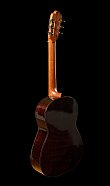
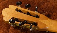
Jump to:  
Powered by phpBB® Forum Software © phpBB Group
phpBB customization services by 2by2host.com