Official Luthiers Forum! http://www.luthiersforum.com/forum/ |
|
My New Saddle Mill http://www.luthiersforum.com/forum/viewtopic.php?f=10102&t=11484 |
Page 1 of 2 |
Author: | Louis Freilicher [ Mon Apr 02, 2007 2:44 pm ] |
Post subject: | |
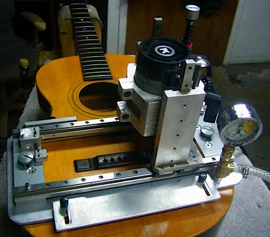
Ever since I saw Frank Ford's Precision Saddle Mill I have wanted to make my own. I finally collected all the bits and pieces I needed and built my own version of Frank's tool. 
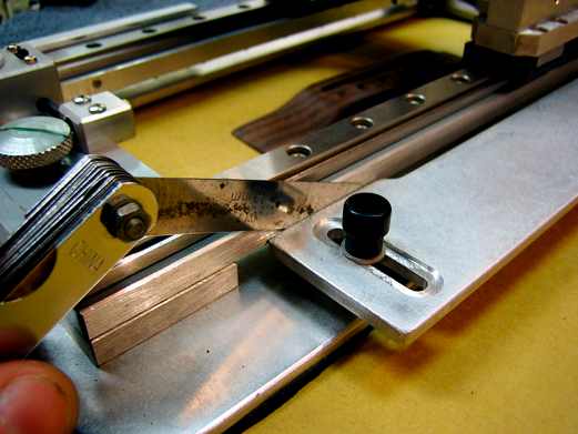
The mill slides back and forth on two linear bearings running on 5/8" rails with stop collars to limit the cutting length. The up and down motion is from a linear slide I picked up on EBay. I'm not sure what type it is, but it was the right dimension for the project. The up and down travel is about 1.5".
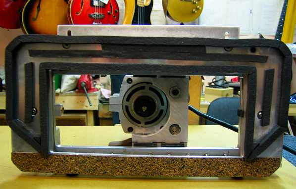
 Here she is: ![]() 
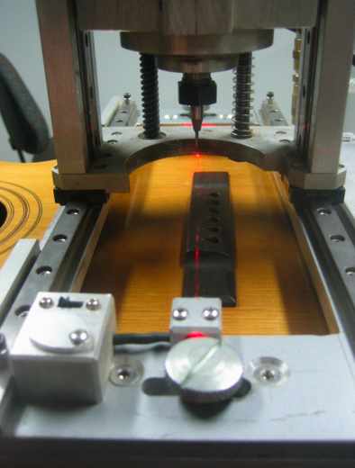
The red circle is the collar that limits the side to side motion. ![]() 
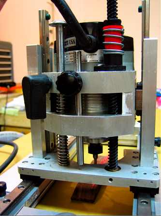
The up and down motion and the cutting depth are adjusted up here. ![]() First, I made up this little step block. ![]() I slip the step block with the depth I want to cut under the height adjustment screw and lower the cutter until it touches the bridge. Then I lock the height adjustment screw with the set screw sticking out towards the back. Now I can fire up the router, remove my little block and plunge the cutter to a known depth. 
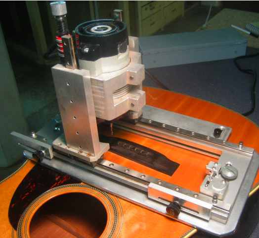
So far this rig has worked out very well. It is very stable and if need be, I can go back and deepen my cut without widening the slot. Enjoy! Louis |
Author: | A Peebels [ Mon Apr 02, 2007 3:22 pm ] |
Post subject: | |
That's nice. Looks like a well thought out tool that will be perfect for the job. Al |
Author: | Louis Freilicher [ Mon Apr 02, 2007 4:29 pm ] |
Post subject: | |
Thanks Al. Since the picture function is back up I'll add one of the rig at work. ![]() And the final product. ![]() Louis |
Author: | JBreault [ Tue Apr 03, 2007 12:01 am ] |
Post subject: | |
That looks really slick Louis. How do you set the angle of the saddle slot? |
Author: | Dave Anderson [ Tue Apr 03, 2007 12:12 am ] |
Post subject: | |
Yes! Very good job on the new tool Louis. Nice job on the old Gibson slot too! |
Author: | crazymanmichael [ Tue Apr 03, 2007 1:14 am ] |
Post subject: | |
nice job of replacing the execrable adjustable saddle on the gibson(?). i notice that you used considerabley less compensation angle than gibson did. comments? |
Author: | Louis Freilicher [ Tue Apr 03, 2007 1:58 am ] |
Post subject: | |
Thanks for the replies all. The guitar is a 50's Gibson that originally had the adjustable saddle. Someone had already removed the metal saddle and inserted an ebony plug but left all the hardware in the top. I removed the bridge and adjustment hardware and glued a rosewood plug into the bridge before I re glued it. Joe- The angle of the slot is set by placement of the rig. I measure out and mark the top of the bridge for the new slot, then loosely clamp the rig to the guitar and wiggle things around until the pencil line lines up with the center of the router bit as I slide it from side to side. Michael- The original bridge footprint was a few degrees off perpendicular to the centerline of the top and to cover a few old boogers I squared it up a bit. My usual compensation calculation is to measure the 12th fret distance, multiply by 2, add .1 and mark that distance between the D and G strings on the bridge. For the low E I add .175; for the high e I use the mathematical scale length. Then connect the dots on the bridge and set up the mill as above. Louis |
Author: | David Collins [ Wed Apr 04, 2007 1:52 pm ] |
Post subject: | |
Regardless of how much time or money it took to make, you will never cease to be glad to have a good saddle routing tool like that. I made one of a slightly different design a while ago and use it quite often, even just for cleaning up sloppy slots. In fact I have two saddle slots that I look forward to the pleasure of routing in the morning. ![]() Having the right tools can make jobs like this so much easier. Nice work on the mill. |
Author: | Anthony Z [ Wed Apr 04, 2007 3:07 pm ] |
Post subject: | |
Very cool set-up! Thank you for sharing. |
Author: | David Collins [ Thu Apr 05, 2007 1:46 pm ] |
Post subject: | |
My mill is of a different design, but here's a few shots. The main points are the same (1/4" shank lam trimmer cutter, linear bearing travel and plunge, width and depth stops) with a slightly different layout. Here is a top/side view on a new bridge I had to slot this morning. I know it's a bit silly and superfluous, but I just couldn't resist taking the bulb and lense from a cheap laser level and mounting it on the carriage. ![]() Here is the back with a lead screw for plunging on the right, a depth stop in the middle, and a spring balance with a lock lever on the left which I never really use. This is a shot of the other side with a view of the end stops that I use. This slot I had to widen out and clean up this afternoon. And on the front side put another stop for odd width slots that may require moving the carriage for a second parallel pass. When I made this I thought for sure that I had spent way too much time and money in making this tool. Now that I've been using it though I can't imagin going without it. Making a good laminate trimmer saddle mill is an investment you will always be thankful that you made. |
Author: | David Collins [ Thu Apr 05, 2007 1:53 pm ] |
Post subject: | |
Sorry, I knew that the photo posting wouldn't work with Safari on my Mac, but it looks like the forum software doesn't agree with Mac Explorer either. I guess I'll have to try downloading Firefox for this forum. |
Author: | SniderMike [ Thu Apr 05, 2007 4:29 pm ] |
Post subject: | |
David, I have that same problem too. I find that if I rename my jpgs a single character name, such as x.jpg, they fit into one line and show up properly. |
Author: | Louis Freilicher [ Thu Apr 05, 2007 5:23 pm ] |
Post subject: | |
Aww Rats, I want to see your mill David. After I cut my first slot with the mill I kicked myself for waiting this long to build it. A .093 slot from a .093 bit.... Finally! There is some time and money to invest in such tooling but it is worth every minute and dollar spent. Please try and post those pics again. Louis |
Author: | David Collins [ Fri Apr 06, 2007 12:57 pm ] |
Post subject: | |
Okay, I got it working, kind of. With the file name shortened to one letter it will work, but if I add any text lines between the third and fourth photos, it will shift all the links to two lines. Weird..... Anyway, captions are as listed above. ![]() ![]() ![]() ![]() ![]() |
Author: | Anthony Z [ Fri Apr 06, 2007 2:59 pm ] |
Post subject: | |
That sure is a fancy set-up. I am looking for the "Patent Pending" stamp on that machine. Did you machine all the parts yourself David. |
Author: | Todd Rose [ Sun Apr 08, 2007 4:17 am ] |
Post subject: | |
Louis and David, I can't see from your photos how you account for the curvature of the guitar top in the way the bases of your jigs sit on the guitar, to ensure a slot of even depth. Whether it's a brand new guitar with a spherically domed top, or an older guitar that can have all sorts of interesting topography from years of distortion under string tension... what's your mechanism for setting up your jig so that it sits stable and in the plane you want it in? Thanks for posting the pics! |
Author: | Louis Freilicher [ Mon Apr 09, 2007 8:29 am ] |
Post subject: | |
David, That is some fine machining on the mill there, excellent work all around and a very well thought out design. I guess that sometime in the future I will want to adapt my machine to be able to widen slots while with precision. It looks like your rig has a vacuum clamp built into the bottom? I lined the bottom of my rig with two layers of gasket sealing cork available at the hardware store etc. This seems to work well and keeps it from skidding around. The base plate is flat so it does flatten out the domed tops a bit, I try not to over-clamp the rig and my guess is that any distortion in the cutting depth is minimal. I would rather have the rig be super stable than find out what happens if the bridge is left to vibrate while the router is running. Louis |
Author: | Dave-SKG [ Mon Apr 09, 2007 10:03 am ] |
Post subject: | |
Louis, I really like your jig. Plan on offering any for sale? If so sign me up! David, that thing looks like something precise enough for NASA...Amazing...WOW! you guys are very creative. D |
Author: | David Collins [ Mon Apr 09, 2007 12:27 pm ] |
Post subject: | |
Thanks guys. I have had several people want to buy it, but I don't currently plan on making any more of these. The time I had to put in to it would make it rediculously expensive, and I keep busy enough with fixing guitars. Perhaps someone should get in touch with Bishop Cochran to suggest making a carriage with these features for his PC310 plunge base. He's certainly a much better machinist than myself, although I'd guess he would have to charge at least $1200-$1500 or more for the whole setup. With how slow I am at layout and setup I would have to charge even more. There's a lot of different ways I'm sure to make a tool to do everything this does. I'm sure there would be ways to adjust Louis mill the allow for the same features. As to the flexing of the top when it is clamped down, I've haven't been too concerned with it. The base is flat with about 1/2" of padding to seal and fit contours, but under vacuum It locks down very firmly and will indeed flatten a top slightly. Still, I don't think any significant or measurable amount of flattening occurs to the bridge itself that could result in a curved slot. At the 2 1/2"-3" span where the slot is set you have a thickness of about 1/2" to 9/16" of maple spruce and ebony laminated, and I believe most of the flattening will occur from the wings outward leaving the saddle region relatively unaffected. It is a good point to bring up though, and I should probably check the change under clamping pressure. I have a 4' straightedge with a .0001" dial indicator in the center that I'll use to check deflection next time I cut a slot. I was going to post a shot of the vacuum clamping bottom of the base, but for some reason I can't get the image link to fit on one line in the text box today. Maybe I'll try again tomorrow. |
Author: | David Collins [ Mon Apr 09, 2007 12:32 pm ] |
Post subject: | |
![]() There, I got it to work. Louis, I meant to ask how long or difficult you felt it was to make that mill. I have a tendency to over-engineer some things, which is probably why my mill would be to costly to produce. Perhaps you should consider making some to sell if you think it's doable - It looks like you have at least one buyer already lined up. ![]() |
Author: | Arnt Rian [ Mon Apr 09, 2007 9:27 pm ] |
Post subject: | |
Well, I'm not showing another jig again! Great stuff, guys. |
Author: | Louis Freilicher [ Tue Apr 10, 2007 10:40 am ] |
Post subject: | |
David, Thanks for posting that bottom shot with the vacuum seals. I built one of the Joe Woodworker vacuum clamping systems but have yet to fully integrate it into my shop. Again being an eBay scroung-o-holic I may have wound up with a vacuum pump that is slightly underpowered for what I'm asking it to do. The mill was also a scrounged up project that took on design changes as I acquired the parts. I built the base and attached the rails before I found the slide way that controls the up and down motion. Once I had all the pieces and a pretty good idea how I wanted it to work the assembly was not too difficult. I did not spent much time milling very piece to a fine finish, basically I ground and filed off the band saw marks and rounded off all the sharp edges and called it good enough. This was basically my first real machining project and I have a lot more to learn. Watch out, machining is as addictive as lutherie! If I had to estimate a budget in terms of money and time I would say $150 in parts and about 6 hours work. If I were to build it again I could probably cut the build time in half but the parts budget would depend on what's available to scrounge this week. This may be common knowledge but for those of you thinking about building a rig like this or something else; aluminum cuts at the same speed as wood. Your blades will wear a bit faster but you can work this stuff on the band saw, table saw, drill press and sander you already own. Dave SKG- I would be glad to work up a mill for you drop me a PM or you can email me from my site. Louis |
Author: | Todd Rose [ Tue Apr 10, 2007 12:25 pm ] |
Post subject: | |
David and Louis, thanks for addressing my question. David, I hadn't even though about the possibility of flexing the bridge downward a bit (as a result of flattening the top somewhat) while routing, and thus ending up with a saddle slot whose bottom has a slight convex curved when you remove the rig... but, now that you mention it, I'm reminded of a "Trade Secrets" email from Dan Erlewine in which he describes his method of using a jack inside the guitar, lifting the bridge area to simulate the convex bridge-flexing effect of string tension, while routing the saddle slot, so that the slot bottom will be truly flat when the guitar is strung up. When I read that I wondered whether that is a common practice among repair people; or, conversely, whether slightly curved-bottom saddle slots resulting from not using some such method are a common problem. |
Page 1 of 2 | All times are UTC - 5 hours |
Powered by phpBB® Forum Software © phpBB Group http://www.phpbb.com/ |